PILE FOUNDATION
Introduction
A
pile is basically a long cylinder of a strong material such as concrete that is
pushed into the ground to act as a steady support for structures built on top
of it.
Pile foundations are used in the following situations:
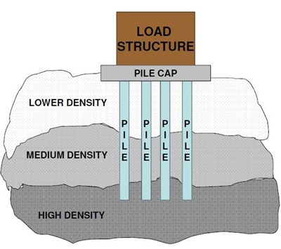
- 1 When there is a layer of weak soil at the surface. This layer cannot support the weight of the building, so the loads of the building have to bypass this layer and be transferred to the layer of stronger soil or rock that is below the weak layer.
- When a building has very heavy, concentrated loads, such as in a high rise structure, bridge, or water tank.
Pile foundation is required when the soil bearing capacity is not sufficient for the structure to withstand. Pile foundations are capable of taking higher loads than spread footings.This is due to the soil condition or the order of bottom layers, type of loads on foundations, conditions at site and operational conditions.
Many factors prevent the selection of surface foundation as a suitable foundation such as the nature of soil and intensity of loads, we use the piles when the soil have low bearing capacity or in building in water like bridges and dams
A pile foundation consists of two components: Pile cap and single or group of piles. Piles transfers the loads from structures to the hard strata, rocks or soil with high bearing capacity. These are long and slender members whose length can be more than 15 m.
Piles can be made from concrete, wood or steel depending on the requirements. These piles are then driven, drilled or jacked into the ground and connected to pile caps. Pile foundation are classified based on material of pile construction, type of soil, and load transmitting characteristic of piles.
The use of pile foundations as load carrying and load transferring systems has been for many years. Timber piles were used in early days, driven in to the ground by hand or holes were dug and filled with sand and stones. The use of steel pile started since 19th century and concrete piles since 20th century.
With the change in technology and industrial revolution, many advance systems have been developed for pile driving from the invention of steam and diesel pile driving machines.
The use of pile foundations is increasing day by day due to non-availability of land for construction. Heavy multistory building are being constructed, and load from these structures can not be directly transferred to ground due to low bearing capacity issue and stability issues of building during lateral load application. So, demand for use of pile foundations are increasing day by day. Due to this demand for piles, there have been many improvements in piles and pile driving technology and systems. Today there are many advanced techniques of pile installation.
Function of Pile Foundation:
As other types of foundations, the purpose of pile foundations is:
– To transmit the buildings loads to the foundations and the ground soil layers whether these loads vertical or inclined
– To install loose cohesion less soil through displacement and vibration.
– To control the settlements; which can be accompanied by surface foundations.
– To increase the factor of safety for heavy loads buildings

The selection of type of pile foundation is based on site investigation report. Site investigation report suggests the need of pile foundation, type of pile foundation to be used, depth of pile foundation to be provided. The cost analysis of various options for use of pile foundation should be carried out before selection of pile foundation types.
Unless the ground condition is rocks, for heavy construction and multistory buildings, the bearing capacity of soil at shallow depth may not be satisfactory for the loads on the foundation. In such cases, pile foundation has to be provided. The number of piles in a pile groups required is calculate from the pile capacity of single pile and the loads on the foundation. Piles are a convenient method of foundation for works over water, such as jetties or bridge piers.
There are
two types of pile foundations, each of which works in its own way.
End Bearing Piles
In end bearing piles, the bottom end of the pile rests on a layer of especially strong soil or rock. The load of the building is transferred through the pile onto the strong layer. In a sense, this pile acts like a column. The key principle is that the bottom end rests on the surface which is the intersection of a weak and strong layer. The load therefore bypasses the weak layer and is safely transferred to the strong layer.
Friction piles work on a different principle. The pile transfers the load of
the building to the soil across the full height of the pile, by friction. In
other words, the entire surface of the pile, which is cylindrical in shape,
works to transfer the forces to the soil.
To visualize how this works, imagine you are pushing a solid metal rod of say 4 mm diameter into a tub of frozen ice cream. Once you have pushed it in, it is strong enough to support some load. The greater the embedment depth in the ice cream, the more load it can support. This is very similar to how a friction pile works. In a friction pile, the amount of load a pile can support is directly proportionate to its length.
To visualize how this works, imagine you are pushing a solid metal rod of say 4 mm diameter into a tub of frozen ice cream. Once you have pushed it in, it is strong enough to support some load. The greater the embedment depth in the ice cream, the more load it can support. This is very similar to how a friction pile works. In a friction pile, the amount of load a pile can support is directly proportionate to its length.
What are piles made of?
Piles
can be made of wood, concrete, or steel.

In traditional construction, wooden piles were used to support buildings in areas with weak soil. Wood piles are still used to make jetties. For this one needs trees with exceptionally straight trunks. The pile length is limited to the length of a single tree, about 20 m, since one cannot join together two tree trunks. The entire city of Venice in Italy is famous for being built on wooden piles over the sea water.
Cross sections of various pile foundations
Concrete piles are precast, that is, made at ground level, and
then driven into the ground by hammering - more on that later. Steel H-piles
can also be driven into the ground. These can take very heavy loads, and save
time during construction, as the pile casting process is eliminated. No
protective coating is given to the steel, as during driving, this would be
scraped away by the soil. In areas with corrosive soil, concrete piles should
be used.
How piles are used
As pile
foundations carry a lot of load, they must be designed very carefully. A good
engineer will study the soil the piles are placed in to ensure that the soil is
not overloaded beyond its bearing capacity.
Every pile has a zone of influence on the soil around it. Care must be taken to space the piles far enough apart so that loads are distributed evenly over the entire bulb of soil that carries them, and not concentrated into a few areas.
Every pile has a zone of influence on the soil around it. Care must be taken to space the piles far enough apart so that loads are distributed evenly over the entire bulb of soil that carries them, and not concentrated into a few areas.
Engineers
will usually group a few piles together, and top them with a pile cap. A pile
cap is a very thick cap of concrete that extends over a small group of piles,
and serves as a base on which a column can be constructed. The load of this column
is then distributed to all the piles in the group.
How
piles are constructed
Engineers will usually group a few piles together, and top them with a pile cap. A pile cap is a very thick cap of concrete that extends over a small group of piles, and serves as a base on which a column can be constructed. The load of this column is then distributed to all the piles in the group.
Piles
are first cast at ground level and then hammered or driven into the
ground using a pile driver. This is a machine that holds
the pile perfectly vertical, and then hammers it into the ground blow by blow.
Each blow is is struck by lifting a heavy weight and dropping it on the top of
the pile - the pile is temporarily covered with a steel cap to prevent it from
disintegrating. The pile driver thus performs two functions - first, it acts as
a crane, and lifts the pile from a horizontal position on the ground and
rotates it into the correct vertical position, and second, it hammers the pile
down into the ground.
Piles should be hammered into the ground till refusal, at which point they cannot be driven any further into the soil.
Piles should be hammered into the ground till refusal, at which point they cannot be driven any further into the soil.
Special
Piles
Pile
driving is very noisy and causes massive vibrations through the soil. For this
reason, it is sometimes difficult to use them in sensitive locations. For
example, if an operational hospital or science lab is to be extended, driving
piles would cause unwanted disturbance. Their use is also restricted in
residential areas in many countries. The vibrations could also cause structural
damage to older buildings that are close by. In such situations it is possible
to use micro piling or helical piling, neither of which relies
on hammering.
Micro piles or mini piles are small piles that are constructed in the following way:
Step 1: a hole a little larger than the pile diameter and the full length of the pile is dug into the ground using an apparatus like a soil boring machine.
Step 2: a precast concrete pile is lowered or pushed into the hole.
Step 3: a concrete grout is poured into the gap between the pile and the earth.
Helical piles are steel tubes that have helical (spiral) blades attached to them. These can be drilled into the ground, meaning that the pile acts as a giant drill bit, and is rotated and pushed into the ground from above, much like a screw drills into wood. Once the steel pile is driven into the ground, a pile cap is poured on top of the pile to prepare it for the construction above.